

Testing Simple prototypes
/The Designs
Our Modeling Technicians, Will and Andres, designed two simple module-sized boards using the Metamorphosys tools to test basic functions. Will made an Audio VU Meter and Andres made a Temperature Sensor. You may have read about Andres' experience designing the temperature sensor.

VU Meter in Desktop Metamorphosys

Temperature Sensor in Desktop Metamorphosys
Getting the Boards Built and Assembled
After they picked their components, drew their schematics, and applied layout constraints, they got the boards built by OSH Park, and the parts assembled on the board by Small Batch Assembly.

OSH Park

Small Batch Assembly
The boards came back from SBA looking good!

VU Meter (left) and Temperature Sensor (right) Assembled Boards
Testing the Boards
Then, we put them to the test. We powered them up, and both boards passed the smoke test.
Testing the Temperature Sensor
The temperature sensor design has a sensor that converts temperature to analog voltage. As we applied hot air to the sensor, the LED's lit up in a specific order, and then as we put a cold spoon next to it, they went back down. It was a success!

Andres Testing His Temp Sensor
LEDs Powered by Heat on Temp Sensor
Testing the Audio vu meter

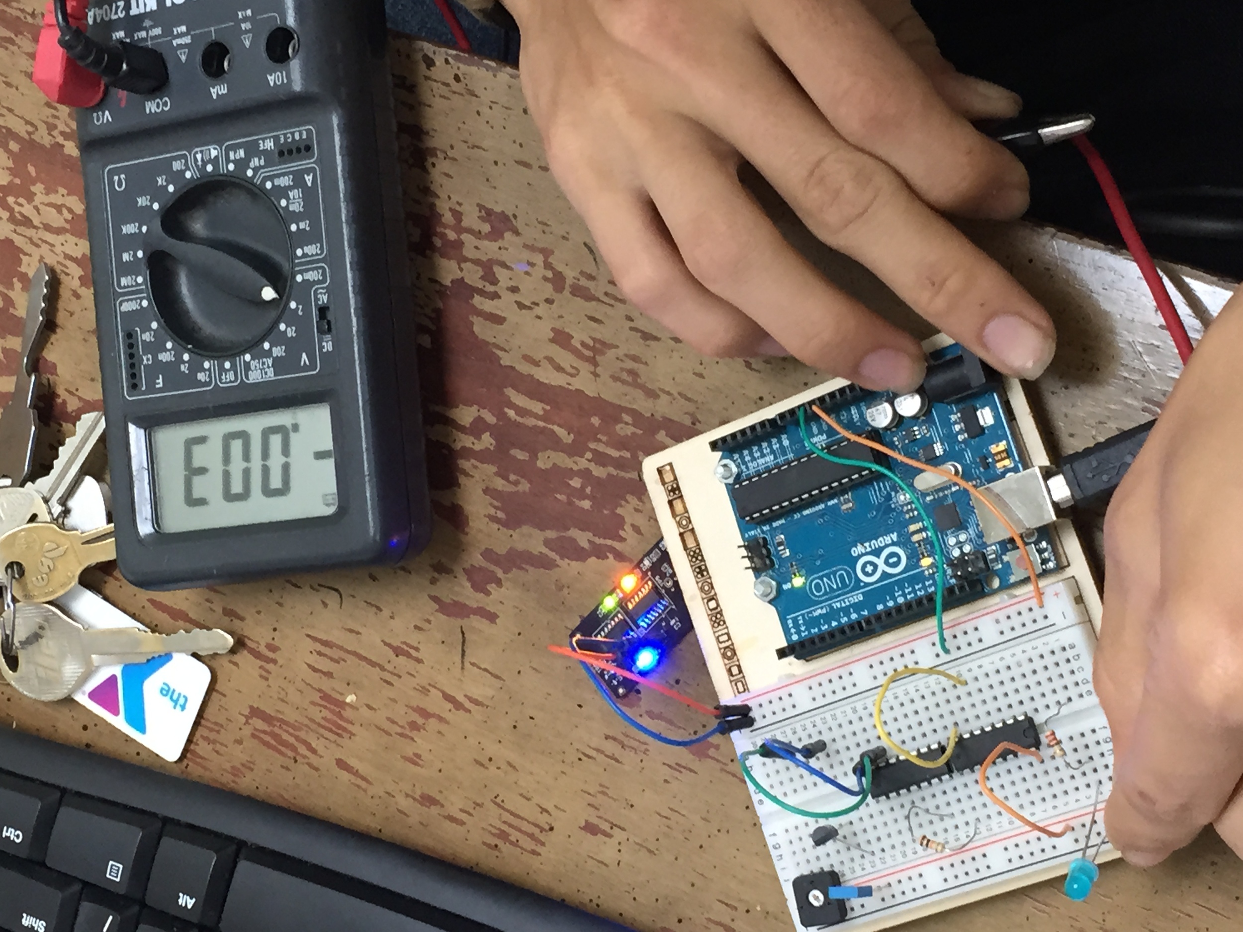
Testing Connectivity on VU Meter

Audio Meter Prototype
Will was not so lucky with his prototype. It powered on, but when the Op Amp detected noise, the LEDs were supposed to light up. Will was clapping his hands, but no LEDs were lighting up. As he investigated the issue, he found that he made a mistake with his design in the Metamorphosys tools by mixing up a V+ and V- connection on the Op Amp.

Mixing up connectors in Desktop Tools
Although the design didn't work, mistakes like this are helping us figure out ways to protect users from making the same mistakes.